Axon Phase — Talaria Sting MX3, MX4 & MX5
Complete installation guide for fitting the Axon Phase controller to the Talaria Sting MX3, MX4 and MX5. Please read all sections before beginning.
Allow yourself a good amount of time. Rushing causes pinched wires and incorrect fitment — both time-consuming to diagnose.
A good set of allen / hex keys is essential. We will not accept responsibility for products or bolts damaged by incorrect tooling.
You are installing an upgrade to an electric motorcycle. If you lack the experience, please seek a professional. Motorcycles can be dangerous when incorrectly installed.
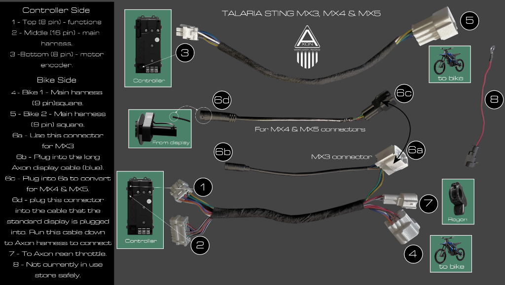
The image below outlines the numbering system used and where each connector is used on the Axon controller harness. When you receive your Axon controller, the harness will have numbers assigned to each connector as shown. You may be left with spare connectors depending on your bike version — tape these up and ignore them. Contact us at info@axon.racing if you have any questions.

Armond has been part of the Sur-Ron / Talaria community in the USA since it began. He has installed the Axon controller on a personal Talaria Sting and documented the stages of installation. Please watch the video guide before you start. Questions? Contact us at info@axon.racing.
The Axon function switches are linked to a number of different functions and ride modes. Below is information on what each button does and how to activate each function.

- —Short press — Toggle hill hold (drive mode only, short term use, not a parking brake)
- —3 second press — Activates or deactivates coasting regen braking when you come off of the throttle
- —Long press 7 seconds — Activate Gyro Mode
- —Short press — Power mode down
- —Short press — Power mode up
- —Long press — Toggle walk mode (great for when you need some help pushing the bike)
- —Short press — Switch between drive and neutral
- —Press & hold — Activates reverse mode. Continue holding for reverse and release for normal drive mode
For product queries or installation help contact us at info@axon.racing